Hydraulic system failures can be difficult to identify and are often challenging to repair. It is thus important to have access to a visual demonstration in order to assist with the error detection process. John Deere has developed a hydraulic system diagram that helps users better understand these issues, as it was highly requested by customers. The newly released diagram offers an explanation of the whole system, as well as solutions for some of the most common hydraulic system fails. This information should help those experiencing any problems feel more secure in their ability to diagnose and fix them.
John Deere Hydraulic System Diagram via Parts Details!
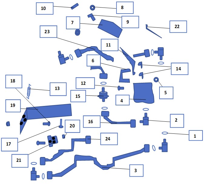
John Deere lawn tractors, along with many other lawn care machines, utilize a hydraulic system to improve ride quality. This complex system is comprised of several parts which work together to achieve its purpose. To better understand the mechanics behind this feature, one can refer to the diagram of John Deere's hydraulic system for a comprehensive overview.

1. O Ring
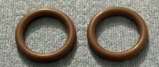
This diagram of the John Deere tractor hydraulic system shows a rubber band situated over an elbow fitting, preventing liquid or gas from entering the path. The rubber band helps keep the connection secure and intact.
2. Elbow Fitting
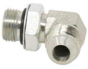
This flex point has been found to provide an effective means of securing the oil tube and hydraulic line. It is able to route both tubes in two different directions, even when limited space is available. This product has proven itself to be a reliable and convenient choice for this application.
3. Oil Tube
This device is composed of a small tube used to transport oil in one direction. It then connects to the lock nut with an elbow fitting and O-ring, providing a secure connection. This mechanism helps ensure that oil flows smoothly and securely through the system.
4. Pressure Relief Valve (PRV)
This relief valve is a handy part that is most commonly known for limiting pressure and ensuring fluid flow at an appropriate level. It provides an essential function in many industries, making it a valuable asset to any operation.

5. Lock Nut
This threaded fastener is designed to be easily lockable using another component. It provides superior security for the subject, preventing any unwanted vibration and providing a tight, secure hold that won't loosen over time.

6. Hook
This piece of equipment has a design that is similar to a U-shaped tool. It serves the purpose of fitting the lever into the pressure relief valve securely with two strong locking pins. This ensures that the valve remains tightly sealed and functions properly.
7. Quadrant
John Deere's hydraulic system diagram illustrates the components of the system, including a lever with a knob, push nut, and insert. This combination allows for precise control of the tractor by providing operators with easy access to simple and effective adjustments. The use of this lever-based system helps ensure that John Deere tractors are capable of meeting even the most demanding tasks.
8. Push Nut
This fastener is an easy and cost-efficient solution for securing components. It requires minimal effort to secure the component, requiring only a simple push. This makes it ideal for connecting shafts and tubes with ease. Its low cost combined with its convenience make this fastener a great choice for any project or repair job.
9. Knob
This lever helps to maintain driver posture by providing an ideal grip. It is designed to fit right above the lever and quadrant, ensuring a comfortable and secure position. This part contributes significantly in keeping the vehicle upright while on the road, thereby reducing fatigue and increasing safety for all passengers.
10. Insert
This pushing part is an essential component that sits on the push nut and knob. Its finish is completed with brushing thereby ensuring strength and durability. It is a reliable piece of equipment that has proved its worth in various settings over time.
11. Lever
This part allows the rider to adjust their gear settings between high and low, depending on their preferred riding style. It is designed to fit onto the relief valve with a single hook attachment.

12. Pin Fastener
This particular component is often referred to as a steel pin, and it has a cylindrical shape. Its purpose is to keep the parts aligned and joint tightly. It serves an important role in ensuring that all components are securely connected and stable.
13. Extension Spring
The extension spring is an integral component of a hydraulic system. It functions to store power and provide pulling energy between two gears. Its operation resembles that of elasticity, as it keeps the two mechanisms close when they attempt to separate. It is thus essential for the smooth functioning of the hydraulic system.
14. Spring Locking Pin
The illustration clearly shows a spring locking pin which serves as a kind of pin to hold the hook in place with its lock mechanisms. This is an important component of the system and it has been designed with precision to ensure that it functions properly and securely.
15. Hydraulic Filter
This hydraulic system component is an essential element for keeping the oil clean and functional for a prolonged period of time. It works to remove dirt and particles from the oil, allowing it to continue operating efficiently. The rapidity of its performance is due to the operation of the pump and motor which generate adequate power.
16. Tube
This tiny part is essential for hydraulic systems to work, as it allows fluids such as gases and oils to pass through. It is made from solid materials like metal that can safely carry hot fluids without breaking down. The empty space inside the part facilitates the passage of these fluids.
17. Bolt
This fitting consists of a head and cylindric body designed to tread a component into the desired place. In order to ensure correct installation, it requires the use of a flange nut for secure attachment.
18. Screw
This bracket is a highly effective and reliable device, designed to hold parts in an appropriate manner. It contains a large tread which twists inside the hole of the bracket to form a strong bond and seal. Typically constructed from metal or wood, it provides the necessary power for secure bonding between components.

19. Bracket
This large frame is constructed using a solid material, such as metal, and contains numerous tiny holes arranged in various directions. Its primary purpose is to secure nuts, screws, and bolts. The structure of the frame allows for strong support and stability for any application that it may be utilized for.
20. Flange Nut
This product is similar to ordinary nuts, but is made with a wider flange that functions like a non-twistable washer. This special feature helps it fit into the tread of the bolt easily and securely.
21. Clamp
This tool is a small and versatile one that assists in the process of securing bolts and brackets with a solid seal by compressing them using a flange nut. Its size makes it ideal for use in tight spaces, while its versatility means it can be used to attach many different types of components. It provides an effective solution with minimal effort needed to achieve the desired outcome of ensuring secure connections between parts.
22. Tie Band
As an OEM part, this rolls up another component, providing a reliable and durable solution. Tie bands are manufactured with heavy-duty plastic or metal to ensure the highest quality and long-term use. This product has been designed to meet all safety standards for both industrial and commercial applications.
23. Hydraulic Hose
The hydraulic hose is an essential component of a hydraulic system, as it shifts fluid between different auxiliary and heavy-working components. Its flexible design makes it well-suited for carrying high-pressure fluids, while its armor ensures that it maintains consistent performance even in the most demanding environments.
24. Hydraulic Line
This part is similar to the hydraulic hose, but has improved heat resistance and is capable of carrying fluid in a specified direction. It provides an effective solution for applications requiring high temperature performance.
Understanding The John Deere Hydraulic System Mechanism
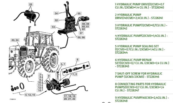
The hydraulic system of a tractor works in an efficient manner. A transfer of fluid is made possible by pumps that link the reservoir and the hydraulic system, increasing pressure and energy level in the process. The pump's power source is a motor, while pressure conversion to mechanical force is done through strokes of a cylinder with rod and piston parts. Once finished, fluids return to the reservoir where heat escapes through its metal walls, reducing overall pressure levels and removing any trapped air from within the fluid.
Common John Deere Hydraulic System Failures to Know About
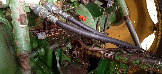
This segment provides information about possible errors that may arise with the hydraulic system, and potential solutions to address them. It is important to remain vigilant regarding any irregularities in the functioning of this system, as these can be indicative of a larger issue that needs attention. In addition, it offers insight into how to prevent further problems from occurring by staying alert for any signs of malfunctions or abnormalities. With such knowledge in hand, individuals can keep their hydraulic systems running smoothly and efficiently.
80% of Hydraulic Failures Happens Because Of
Contamination of air and water can be detrimental to the overall health of a system. Common causes for contamination include breaches in systems, damaged or unusable pumps, and malfunctioning temperatures. Air contamination is another issue that can arise when it enters into the hydraulic system; there are two main types:
- Particulate Contamination – these particles consist of dirt, dust or metal filings which can cause damage to internal components if left unchecked.
- Gas Contamination – this includes any gases that enter the hydraulic system due to improper seals or leaks in the equipment. These contaminants reduce oil viscosity as well as produce corrosion over time if not removed promptly.
Aeration and Cavitation
Hydraulic systems can be damaged by aeration, cavitation and water contamination. All three have their own unique way of damaging the system, but all are equally damaging to the entire system. To ensure that your hydraulic system is working properly, it's important to recognize the symptoms which indicate any form of contamination in the system.
Aeration occurs when air enters into a pump cavity from an outside source such as loose connections or even leakage. Cavitation on the other hand is caused when pumps pull out dissolved air from oil and then cause implosions which again results in damage over time to both components and pumps alike. Lastly, water contamination can occur due to too many leaks in the system or a change in temperature causing condensation; this type of contamination can degrade components if not taken care of quickly enough.
To avoid any problems with your hydraulic systems, make sure you know how each type of contamination works so you can take appropriate measures before they become irreversible issues:
- Wear down on pump and surrounding components
- Overheating issues
- Contamination of hydraulic fluids
- Loose connections for aeration
- Implosion for cavitation
- Leaks for water contamination
Thinning, Oxidization, and Thickening of Fluid is Problematic
Temperature fluctuations in hydraulic systems can cause serious problems. If the fluid is too hot or too cold, it can lead to thinning, thickening, and oxidization of the fluid.
When exposed to heat, hydraulic fluids tend to become thinner over time. This is called fluid thinning and it can have a number of detrimental effects on the system such as interruption with proper lubrication process, increased likelihood of leaks and reduced ability to dissipate heat. It also causes build-ups when fluids thicken due to high temperatures in the system which ultimately leads to flow restrictions and decreased heat dissipation capacity.
On the other hand, if there are temperature drops that cool off the system too much then this could lead to difficulty for oil reaching pumps as well as pressure buildup causing cavitation damage from increased viscosity levels caused by low temperatures. In most cases these issues arise from poor heat dissipation abilities from within the system or external environmental factors causing an overly cold environment around it.
5 Issues Caused By Temperature Fluctuations In Hydraulic Systems:
- Fluid Thinning - Interruption with proper lubricating process; Prone to leaks; Reduced ability for heat dissipation
- Thickened Fluid - Build ups; Flow Restrictions; Difficulty dissipating heat
- Oxidization - Decreased efficiency; Increased wear & tear on parts
- Low Temperature Fluids - Difficulty for oil reaching pump; Pressure buildup leading to cavitation damages
- Poor Heat Dissipation Abilities/Environmental Factors – Overly cold surroundings
Poor Quality & Level of Fluid
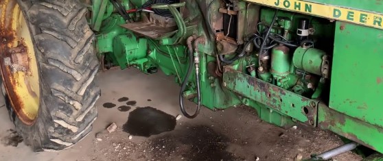
Hydraulic systems can experience a variety of failures, one of which is caused by low quality or insufficient levels of hydraulic fluid. Poor filtration in the system can result in bad air contamination and inadequate oil levels will lead to other problems. It is therefore essential that the correct type of lubricant for each application be chosen carefully.
Today's market offers a range of oils designed to resist temperature-related issues as well as those with anti-foam and wear additives included. By selecting the right product, it is possible to reduce any potential damage due to air contamination and prolonged wear on mechanical parts. Ensuring that these measures are taken should help keep your hydraulic system functioning smoothly over time.
Failures Due to Wrong Usage
Nowadays, many hydraulic system failures can be attributed to user error. Installation mistakes, such as incorrectly placed pump shafts and mismatched parts, are some of the most common sources of system failure. Additionally, careless or incorrect usage of a hydraulic system can cause an array of issues including excessive pressure buildup and damage from exceeding maximum speed limits. To ensure optimal operation and avoid these problems, it is important for users to familiarize themselves with proper techniques for installation and maintenance.
Thankfully, resources are available to help guide users on how best to use their systems without running into any issues. A thorough understanding about the right usage and maintenance processes will help guarantee that your hydraulic system runs at its peak performance. With proper care and knowledge you’ll never have to worry about making simple errors again!
For those just getting started in learning more about properly using a hydraulic system our website offers comprehensive guides designed specifically for beginners that address all aspects necessary for success. If you take advantage of these resources you’ll be well on your way towards mastering the mechanics behind this powerful technology!
Troubleshooting The Hydraulic System – Briefly Explained
It is important to check the system of your John Deere regularly in order to identify any potential failures. The following steps should be taken:
- Turn it on and off - this will test the wiring with the motor.
- Test the pump - disassemble and go through all components, making sure everything is installed properly and meets specifications for fluid levels, color, viscosity etc.
- Check valves and lines - look for leaks or loose connections points, as well as ensuring that relief valve is free from damage
- Run system - observe pressure and temperature fluctuations, abnormal noise, potential fails in pressure sensors etc..
Follow Up with Prevention & Maintenance
- Before investing in any new parts, it’s important to double-check the specification to ensure you are buying something that matches your needs.
- To make the most informed decision, industry professionals recommend consulting with an expert who can help you choose the right equipment for your system.
- One helpful addition is a product designed for hydraulic system protection and failure prevention – such as a locking actuator which stops moving when potential failure is detected.
- Additionally, these products may reduce costs associated with maintenance and repairs by proactively addressing issues before they become problems down the road.
- With quality products designed to protect against failures and increase efficiency, it pays off to invest in reliable parts whose performance will stand up over time and prevent costly downtime or replacements later on down the line.
The John Deere hydraulic system diagram, along with all its relevant information, has been provided to assist in resolving any issues related to this particular system. Although the resources are available, it can still be difficult for some to find a satisfactory solution. If that is the case, professional help should be sought out. Consulting a professional will allow one to quickly and reliably identify an effective solution.
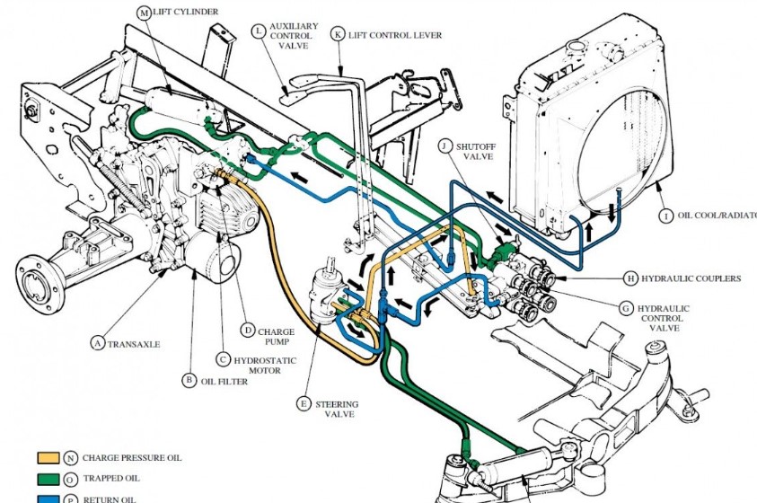

I'm so glad I found this article. As a farmer, I rely on my John Deere tractor for many tasks. It's essential that the hydraulic system works as it should, so I'm always looking for ways to troubleshoot any issues that may arise. This article was so helpful for me in understanding the structure of the hydraulic system and how it all fits together. I also appreciate that it gives me a visual of the flow of oil throughout the system so I can pinpoint any potential weak points.
I think it would be really helpful if the article included some information on troubleshooting potential problems. I've had my fair share of issues with the hydraulic system and have found that understanding the basics of the system can help you easily identify the root of the problem and find a solution. For example, I once had a problem with the oil pump, and after researching the system, I could identify and replace the faulty part.
Does anyone else have any experience with troubleshooting hydraulic system issues? I'd love to hear about it!erkut1John Deere Tractor Hydraulic System Diagramerkut2John Deere Tractor Hydraulic System Diagram